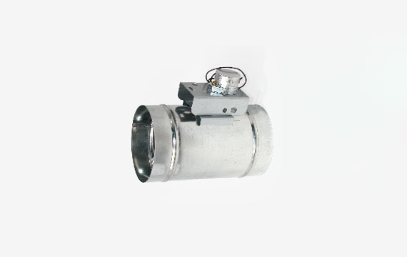
Volume control damper
IRIS
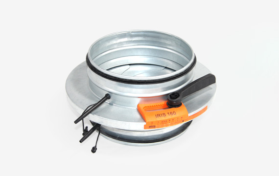

IRIS

| Type | d(mm) | D(mm) | L(mm) | A(mm) | Material THK(mm) |
| 80 | 79 | 125 | 115 | 33 | 0.6 |
| 100 | 99 | 165 | 115 | 27 | 0.6 |
| 125 | 124 | 188 | 115 | 27 | 0.6 |
| 150 | 149 | 230 | 115 | 27 | 0.6 |
| 160 | 159 | 230 | 115 | 27 | 0.6 |
| 200 | 199 | 285 | 120 | 27 | 0.6 |
| 250 | 249 | 335 | 135 | 33 | 0.6 |
| 315 | 314 | 405 | 140 | 33 | 0.6 |
| 400 | 398 | 525 | 150 | 46 | 1.0 |
| 500 | 948 | 655 | 150 | 46 | 1.0 |
| 630 | 628 | 815 | 155 | 46 | 1.0 |
| 800 | 798 | 1015 | 285 | 110 | 1.0 |
|
Regulation and measurement of air flow
The regulation plates form a virtually ideal measuring orifice which enables an easy and reliable measurement of the air flow.
To determine the air flow, measure the pressuredifference Δpm at the manometer connections and check the corresponding air flow from the regulation chart.
The chart is shown on the damper casing and in the separate information for air flow regulation and measurement (the selection diagrams do not serve the air flow measurement).
Air flow is regulated by the regulating nut or handle.
The IRIS damper is secured to the ducting with rivets. For vertical mounting ensure the weight of the interconnecting ductwork is fully supported.
Refer to the form for recommended safety distances.
|

 0086-571-81603539


 Online


